REACTIONTORQUE.COM / ENGINEERING
Reaction Torque Sensor vs. Rotary Torque Sensor
Choose a torque measurement load path: fixed housing or rotating shaft. Review acceleration, friction, bandwidth and parasitic torque before selecting.
MEASURE THE FIXED LOAD PATH
The shaft turns. The sensor stays on the frame.
A Reaction Torque Sensor between a motor or gearbox housing and the fixed frame measures the housing torque without rotating the sensor cable.
For steady-state balance, relate housing torque to shaft torque after accounting for losses and other loads. During acceleration, include rotor inertia and any parallel torque paths. Validate fixture resonance, sensor bandwidth and cross-load limits.
Review fixed-housing vs. rotary measurement ↗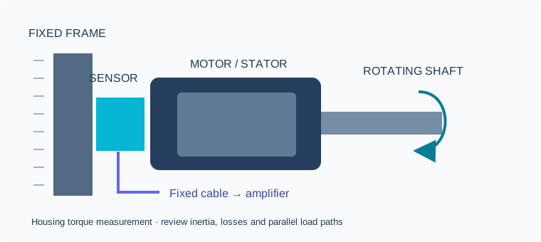
Choose a fixed housing sensor when the load path is accessible.
| Decision | Reaction Torque Sensor | Rotary torque sensor |
|---|---|---|
| Measurement location | Housing / fixed member | Rotating shaft |
| Continuous sensor rotation | No; protect the cable | Designed for rotation within rating |
| Dynamic use | Varying housing torque within system bandwidth | Shaft torque within rated speed and bandwidth |
| Typical integration | Stator mount, valve fixture, joint fixed member | Driveline, dynamometer shaft, rotating tool |
| Critical checks | Parallel paths, inertia, friction, fixture stiffness | Speed, coupling, balance, telemetry and rotor inertia |
Housing torque is not automatically instantaneous output torque.
Draw the free-body diagram for the exact assembly. Acceleration adds an inertial term Jα, and bearings, cables, hoses and supports can create additional torque paths. Gearbox fixed-member measurements require the gearset load path to be understood. Validate the full assembly over the intended load cycle.
Check the rotary design before assuming slip-ring wear.
A stationary sensor avoids rotating contacts in its own signal path. Rotary transducers may use non-contact telemetry or rotary transformers; they do not all use brushes. Choose by the physical measurement task, not a universal lifetime or cost claim.
Reference reading: FUTEK TFF400 manufacturer description and TFF family mounting manual. These describe the referenced equipment, not MT-RTS performance.
REQUEST QUOTE / CAD
Start with your load and mounting envelope.
Send the installation constraints. We will review the sensor configuration, drawing, calibration scope and commercial quotation.
Prefer email? inquiry@reactiontorque.com
Please send non-confidential specifications first. CAD is supplied for the agreed configuration after engineering review.