Flange assembly · independent Fz and Mz bridges
Share the complete mating drawing and available envelope.
MT-RTS-FZ / STATIC TORQUE SENSING
Dual full-bridge Fz / Mz sensing for drilling, tapping, tightening preload studies and combined thrust/torque benches. Specify the load pair and combined-load envelope.
Requested range 1–1,000 Nm + 100 N–50 kN
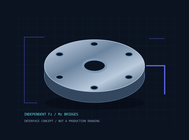
DRAWING REVIEW / CONFIGURATION MATRIX
Series selection envelope, not released model specifications. Request the range-specific drawing and measured stiffness/cross-load limits before design release.
| Model (MT-RTS-xxx) | Rated Torque (Nm / in-lb) | Outer Dia. & Bolt Circle (OD / BCD) | Center Thru-Bore ID (mm) | Torsional Stiffness (Nm/rad) | Max Axial Thrust Limit (N) |
|---|---|---|---|---|---|
| MT-RTS-FZSeries / request code | 1–1,000 Nm8.85–8,850.75 in-lbFz target: 100 N–50 kN | Drawing confirmation | Configuration-specific center opening | Range-specific confirmation | Combined-load review required |
Share the complete mating drawing and available envelope.
Include duty cycle, dynamic peaks and the surrounding fixture.
FUTEK MBA500 · Interface axial-torsion references
Independent comparison only. Original model identity and principle must be checked.
BEFORE SELECTING THE RANGE
Material and signal targets: 17-4PH stainless or 7075-T6 aluminum; 1.5–2.0 mV/V nominal full-bridge output; CW/CCW calibration. The requested ±0.05–0.1% FS nonlinearity/hysteresis target requires range-specific verification. Temperature effects, excitation, overload, IP rating and cross-axis sensitivity are confirmed per configuration.
MEASURE THE FIXED LOAD PATH
A Reaction Torque Sensor between a motor or gearbox housing and the fixed frame measures the housing torque without rotating the sensor cable.
For steady-state balance, relate housing torque to shaft torque after accounting for losses and other loads. During acceleration, include rotor inertia and any parallel torque paths. Validate fixture resonance, sensor bandwidth and cross-load limits.
Review fixed-housing vs. rotary measurement ↗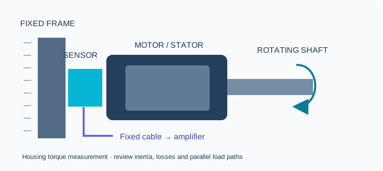
ENGINEERING QUESTIONS
Yes, when the sensor remains stationary and the varying housing load is within the complete measurement system bandwidth. Review inertia, losses, resonances and other torque paths before relating it to shaft output.
No. Approve the range-specific mechanical drawing, stiffness, cross-load limits, excitation, sensitivity and connector wiring before a replacement is released.
Request five points in both CW and CCW, the sensor/readout pairing, uncertainty and the traceability chain. The quotation confirms the actual report scope; NIST traceability is not a blanket product certification.
REQUEST QUOTE / CAD
Send the installation constraints. We will review the sensor configuration, drawing, calibration scope and commercial quotation.
Prefer email? inquiry@reactiontorque.com
Please send non-confidential specifications first. CAD is supplied for the agreed configuration after engineering review.
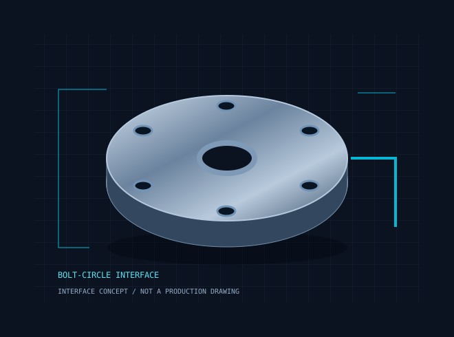
0.5–5,000 Nm
Motor stator and valve actuator test stands02 / MT-RTS-JNT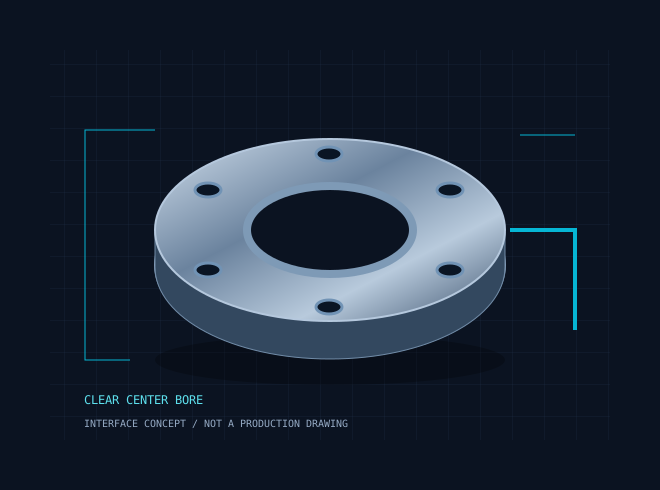
1–500 Nm
Humanoid, exoskeleton and surgical robot joints03 / MT-RTS-SQ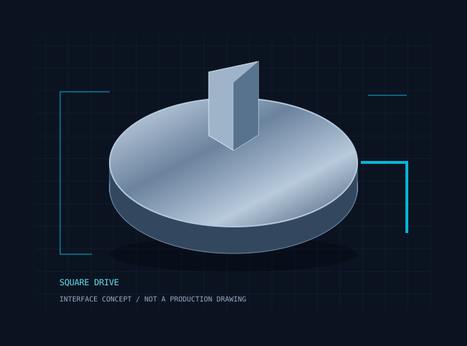
1–2,000 Nm
Torque-tool and fastener calibration fixtures04 / MT-RTS-SHF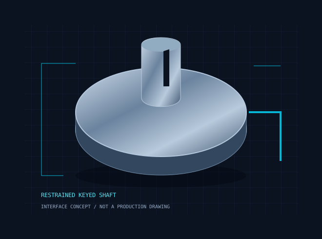
0.1–1,000 Nm
Bearing friction and low-torque component tests05 / MT-RTS-FZ1–1,000 Nm + 100 N–50 kN
Drilling, tapping and fastener preload correlation