1 / Fixed sensor bridge
EX+ / EX− supply the bridge. SIG+ / SIG− carry its small differential output. Optional SENSE+ / SENSE− report excitation at the bridge.
REACTIONTORQUE.COM / ENGINEERING
Connect a fixed torque sensor to a bridge amplifier: excitation, mV/V scaling, four-wire or six-wire functions, polarity and signal-chain verification.
By ReactionTorque.com · Engineering guide · Reviewed
A strain gauge torque sensor converts elastic strain into a bridge signal. This guide covers a fixed, cabled industrial torque transducer. The sensing principle alone does not make a sensor static: Kistler’s 4502A is a strain-gauge shaft sensor with non-contact signal transfer.
If the sensor body must rotate continuously, first use the fixed-housing versus rotating-shaft selection guide. For a stationary body, assemble the sensor drawing, range-specific report, cable diagram and conditioner manual before wiring.
FUNCTIONAL SIGNAL PATH / NO CONNECTOR PIN ASSUMPTIONS
EX+ / EX− supply the bridge. SIG+ / SIG− carry its small differential output. Optional SENSE+ / SENSE− report excitation at the bridge.
Match excitation and input limits. Amplify and filter the differential signal; apply the sensor’s documented sensitivity and zero.
Receive the specified analog or digital output. Record units, CW/CCW sign, scaling, filter, sample rate and timestamps.
This is a function diagram, not a pinout. A digital or amplified sensor output needs its matching input, rather than a second raw-bridge conditioner. PCB’s sensor manual, §§4–7, calls for both the sensor installation drawing and conditioner wiring drawing.
| Function | Four-wire bridge | Six-wire bridge / acceptance check |
|---|---|---|
| EX+ and EX− | Excitation pair | Same supply function; verify allowed voltage and conditioner current capacity |
| SIG+ and SIG− | Differential signal pair | Same measurement function; check differential and common-mode input limits |
| SENSE+ and SENSE− | No separate remote-sense pair | Sense excitation at the bridge when supported by both sensor and conditioner |
| Shield / case | Follow the documented shielding arrangement | Separate from signal return; termination and grounding follow the system drawing |
| Connector identification | Record mating view, numbering and wire functions | Record sense connections too; neither color nor physical connector fit proves compatibility |
Long excitation leads can reduce voltage at the bridge. A supported six-wire arrangement measures that voltage using a separate sense pair. Follow the conditioner’s four-wire instructions if remote sense is unavailable; do not invent jumpers. See NI’s full-bridge remote-sense explanation and Beckhoff’s excitation/sense distinction.
ILLUSTRATIVE ARITHMETIC / NOT AN MT-RTS RATING
Assume an illustrative 100 Nm range, sensitivity S = 2.0 mV/V, and 5.0 V measured excitation at the bridge. The zero-subtracted full-range output is 2.0 × 5.0 = 10.0 mV. Half range would produce 5.0 mV in an ideal linear example.
T = [(Vsignal − Vzero) / Vexcitation] ÷ S × Trated. Use mV for signal, V for excitation and mV/V for S. With +5.0 mV after zero subtraction: (5.0 / 5.0) / 2.0 × 100 = +50 Nm.
A −5.0 mV signal gives −50 Nm under the same sign convention. It does not independently establish CW or CCW: define the viewing direction and confirm polarity against the ordered report. An unloaded +0.2 mV offset would equal +2 Nm in this example if left uncompensated.
These inputs are calculation examples, not excitation permission, a supplied sensitivity or a guaranteed accuracy. Use the actual report, scaling and calibration coefficients. Two mV/V is a ratio, not a 2 V output or a digital communication format.
| Record from the sensor / cable | Confirm at the conditioner / DAQ | Why it changes the result |
|---|---|---|
| Allowed excitation; input bridge resistance | Supply voltage, current budget and supported bridge configuration | Avoid unsupported excitation or a source that cannot drive the bridge |
| Rated mV/V, zero balance and CW/CCW response | Bipolar differential range, offset headroom and scaling | Prevent saturation or a reversed / mis-scaled reading |
| Output resistance, cable length and shielding | Input compatibility, sense scheme and grounding | Control loading, lead effects and interference |
| Torque rise time / frequency of interest | Effective bandwidth, sample rate, anti-alias filtering and output update | A fast bus does not establish usable transient response |
| Required PLC / PC / controller connection | Output voltage/current range or digital profile and host support | USB, CANopen, EtherCAT and SPI identify interfaces, not one interchangeable module |
Compare the commercial readout and amplifier kit requests after these input checks. For Fz/Mz hardware, define two independently scaled, synchronized channels and the combined-load review on the biaxial sensor page.
A specified shunt resistor unbalances the bridge to produce a reference electrical response. It can help check conditioner gain and continuity of the included signal path. It does not apply a known physical torque or prove mechanical sensitivity after overload. PCB distinguishes system calibration from shunt calibration.
For strain gauge torque measurement acceptance, define the physical input, directions, loading sequence, sensor/cable/electronics configuration and uncertainty. Preserve the unloaded reading before tare; a successful zero command does not establish span. Use the recalibration and as-found evidence guide when a cable, readout, mounting or sensor history changes.
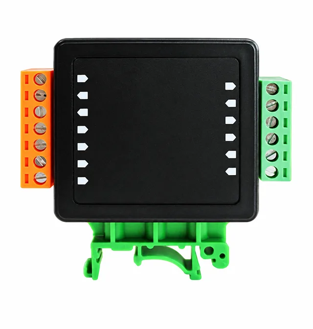
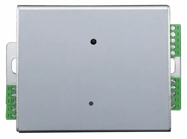
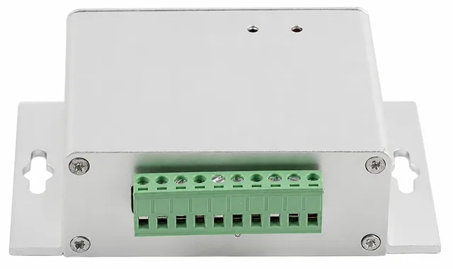
A raw bridge needs compatible excitation and a suitable bridge input or conditioner. Select the conditioner’s input and output separately; a PLC voltage input is not automatically a bridge measurement input.
No universal assignment is used here. Match function labels to the actual sensor and conditioner drawings, including the connector mating view and shield. Request missing documentation before connecting power.
REQUEST QUOTE / CAD
Send the installation constraints. We will review the sensor configuration, drawing, calibration scope and commercial quotation.
Prefer email? inquiry@reactiontorque.com
Please send non-confidential specifications first. CAD is supplied for the agreed configuration after engineering review.
SIGNAL CONDITIONING / SUPPLIER REFERENCES