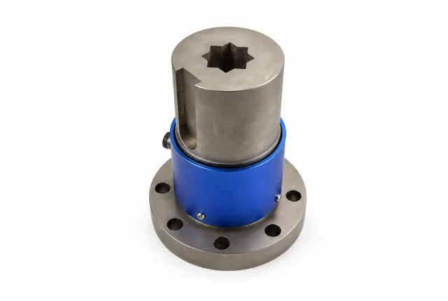
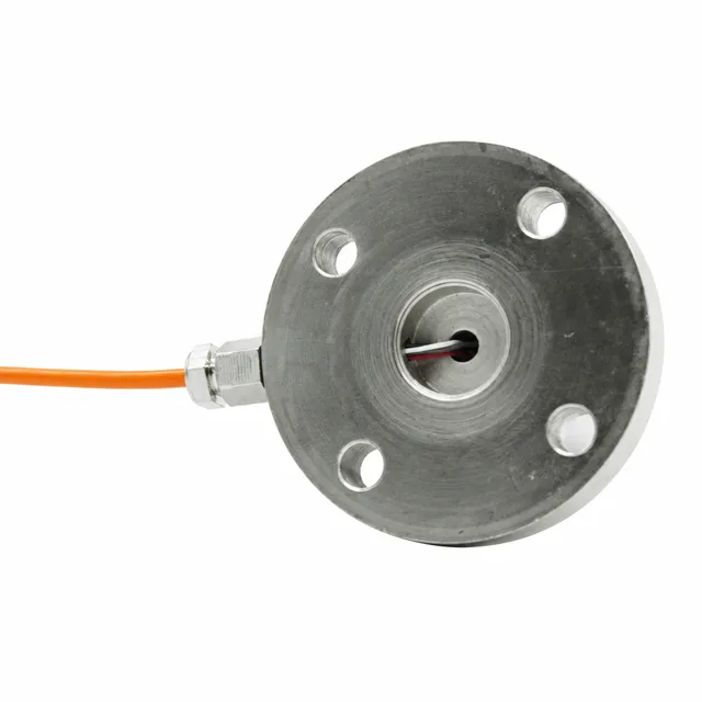
1 / Identify the trigger
Scheduled review, suspected overload, repair, unstable zero, unusual handling or changed electronics. Record when the issue appeared and the last known valid check.
REACTIONTORQUE.COM / ENGINEERING
Plan industrial torque sensor recalibration using measurement history, as-found data and the complete signal chain. Prepare a documented engineering review.
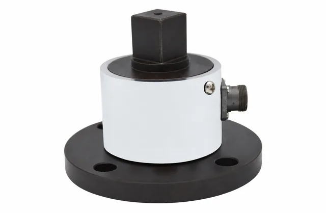
By ReactionTorque.com · Engineering guide · Reviewed
Torque sensor recalibration compares an existing industrial measurement response with a defined reference and uncertainty. Start with the result you need to trust, the sensor history and the signal chain actually used.
This guide covers industrial static torque transducers and their instrumentation. Requests are reviewed for feasible scope before quotation. A new-kit calibration option does not establish service availability for an arbitrary third-party sensor or an accredited laboratory capability.
| Check | What is observed | What it does not establish |
|---|---|---|
| Unloaded zero / tare | The indicated baseline in a defined unloaded state | Span, hysteresis, mechanical integrity or traceability |
| Electrical shunt verification | The response to a specified electrical bridge imbalance in the included path | A response to known applied torque or the condition of the load-bearing structure |
| Physical torque calibration | Response to reference torque over agreed points, directions and configuration | Every installed load case, untested bandwidth or an automatic pass outside the stated scope |
PCB’s system-versus-shunt explanation distinguishes applying physical loads to a system from simulating a bridge output electrically. Record which check was performed, with what reference and in which configuration.
HISTORY / REQUIREMENTS / ENVIRONMENT
NIST’s interval guidance does not prescribe a general fixed recalibration interval. It identifies accuracy needs, contractual or regulatory requirements, instrument stability and environment as relevant factors. It recommends measurement-assurance records to characterize behavior and refine the interval using subsequent reports.
Start with the applicable manufacturer instructions and your quality-system requirements. Record intermediate checks, use severity and uncertainty needs. Review the interval when as-found results approach limits, drift changes or the measurement consequences change. Keep the responsible quality owner and the review rationale in the equipment record.
Manufacturer schedules remain model-specific. For example, Interface’s TS manual, §§7 and 11, specifies its own schedule and calls for shorter intervals after overload, repair or inappropriate handling, and for demanding quality or traceability needs. That schedule is not a universal interval for MT-RTS configurations.
Scheduled review, suspected overload, repair, unstable zero, unusual handling or changed electronics. Record when the issue appeared and the last known valid check.
Keep original readings, report, serial IDs, settings, tare state and temperature. Route affected measurements through your quality process before overwriting offsets.
Choose sensor-only or the complete chain. Agree directions, points, uncertainty, report content and any adjustment authorization with the qualified provider.
| Trigger | Evidence to retain | Review question |
|---|---|---|
| Suspected overload or mechanical damage | Peak history, fixture incident, zero shift and observed condition | Is evaluation / repair needed before any calibration? |
| Cable, amplifier or readout replacement | Old/new component IDs, lengths, wiring, excitation and scaling | Does the existing report cover the changed measurement chain? |
| Drift, poor repeatability or changed zero | Unadjusted readings, temperature, mounting and check-reference records | Is the cause mechanical, electrical, environmental or metrological? |
| Quality / customer requirement changes | Allowed error, uncertainty requirement, procedure and reporting criteria | Are the range, directions and laboratory scope still suitable? |
A sensor report expressed in mV/V is not the same record as a complete chain displayed in Nm. A system scope identifies the sensor, supplied cable, conditioner and readout together, including excitation, gain, units, sign, firmware/software settings and filtering used for the result.
Specify CW and CCW directions, viewing reference, loading/unloading sequence, points and zero return. For Fz/Mz, specify both channels, cross-axis requirements and whether simultaneous load combinations are included. A static calibration result alone does not verify an installed controller’s transient capture performance.
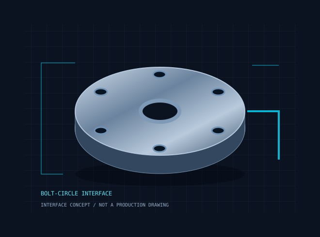
For a replacement readout, first review input matching and system-calibration kit requests. For unknown wiring, use the excitation, mV/V and bridge wiring checklist. Describe the fixture on the flange sensor or square-drive tool fixture page.
A NIST traceability request is not a claim that NIST calibrated the sensor. See NIST’s traceability policy for the provider’s responsibility to support the measurement result and its uncertainty chain. An ISO/IEC 17025 request needs the actual laboratory’s applicable scope; no accreditation or third-party service availability is asserted by this guide.
Keep measurement and adjustment separate in the request. Ask for as-found evidence and agree authorization before changes; a provider must first confirm what evaluation, repair or adjustment is feasible.
Zero is one observation. Validity depends on sensitivity, repeatability, load history, the complete chain and acceptance requirements. Your quality process determines the affected interval and disposition of prior results.
REQUEST QUOTE / CAD
Send the installation constraints. We will review the sensor configuration, drawing, calibration scope and commercial quotation.
Prefer email? inquiry@reactiontorque.com
Please send non-confidential specifications first. CAD is supplied for the agreed configuration after engineering review.
IDENTIFY THE COMPLETE ASSEMBLY